
Aspheric lenses have established themselves as a key component across multiple sectors from photography to smartphones, from medical devices to aerospace because they deliver superior optical performance with reduced mechanical complexity. But what does it really mean to adopt an Aspheric lens in a design, and what conditions are needed to achieve optimal results?
In this article we introduce the practical benefits of Aspherics and how Tecnottica Consonni supports customers and designers at every stage of production; we also include a comprehensive section with recommended materials, coating specifications and a checklist of tests and documentation to request from suppliers for the main application sectors: Mobile Imaging, Aerospace, Laser & Industrial.
Why choose an Aspheric lens?
In traditional optical systems, the curvature of spherical lenses generates spherical aberration peripheral rays focus at different points than central rays. To correct this, designers often use multiple lens elements, which increases weight, volume, assembly complexity and can introduce secondary effects such as flare and chromatic aberrations.
Aadopting a single aspheric lens in place of a lens group makes it possible to reduce weight and size, particularly critical in the aerospace sector and in portable devices, improves image contrast and definition with less flare, and allows the design of larger apertures, yielding better performance in low-light conditions. In addition, the aspheric surface is engineered so that each zone of the lens redirects rays appropriately, producing a uniform focal behaviour across the entire useful field and delivering sharper images.
From an application standpoint, these benefits translate into measurable advantages: reduced mass (for aerospace), thinner and lighter camera modules (ideal for smartphones and medical imaging systems) with higher usable resolution. For laser and beam-shaping applications, reducing the number of optical surfaces lowers losses and unwanted reflections, improving beam efficiency and contrast.
Designing and manufacturing an Aspheric lens
Designing and manufacturing an Aspheric lens is inherently more complex than producing a conventional spherical lens. The differences are not only geometric they complicate the entire chain (design, machining, finishing, metrology) and require dedicated skills, equipment and controls at each stage.
 The variable curvature of an Aspheric surface requires dedicated optical and mechanical design. The profile is not described by a single constant radius, but by a function. This means optical CAD and CAM must handle complex shape equations and convert them into machine trajectories at extremely high resolution: every point on the surface has its own curvature and the numerical control must follow it with micron-level often sub-micron precision.
Manufacturing Aspherics therefore requires advanced CNC equipment and sophisticated control software. Unlike a sphere which can be generated by constant, repeatable motions an Aspheric is “built” point-by-point or through highly differentiated cycles; production is largely one-piece-at-a-time.
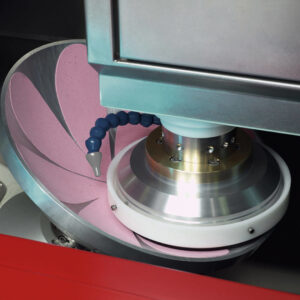 Finishing (polishing) is another critical challenge. To obtain the required shape and surface quality, deterministic and adaptive polishing techniques are used (for example ADAPT technologies): operations are performed on small contact areas and guided by algorithms that adapt action based on measurement. This approach can correct local shape defects but requires tight integration between machine, sensors and control software.
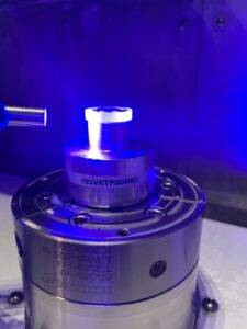
Metrology also plays a central role. Measuring an Aspheric requires dedicated 2D/3D instruments profilometers, scanning interferometers and MWLI technologies, such as the LUPHOScan that provide high-density shape maps. These instruments are not only used for final verification but, crucially, for in-process control: measurements feed back into polishing corrections and close the production cycle within tight tolerances.
Other variables that complicate the process include environmental influences (temperature, humidity, air pressure) and the thermo-mechanical stability of the machines. For micrometric work, temperature controls, low-expansion materials and extensive calibration procedures are adopted. Precise centration and mechanical alignment control are essential as well: positioning errors translate directly into form errors.
At Tecnottica, to manage the full process we have trained highly specialised staff. Technicians, physicists and optical engineers must be able to design the surface, program machines, interpret measurement maps and tune corrections. Understanding the underlying physical phenomena (friction, thermal effects, abrasive behaviour) is often decisive to reduce cycle times and costs.
Practical advice for designers
If you are considering using Aspheric lenses in your project, define spectral specifications (operational band, desired transmission, reflection limits) and operating environment (temperature, humidity, vacuum, thermal cycles, radiation exposure) from the start. These factors determine material selection, coating choices and qualification requirements.
Involve the manufacturer early in the concept phase: early collaboration allows optimisation of geometry, tolerances and production processes (grinding, lapping, polishing) to produce a component that is manufacturable within acceptable cost and lead times.
Schedule a prototyping and test phase (shape measurements, roughness, LIDT where relevant, environmental tests) to establish acceptance criteria and minimise production risks in series. Request detailed metrology reports (instruments used, measurement conditions, uncertainty), because traceability of production data is essential to guarantee repeatable performance in industrial production.
 Common documentation to request
- Technical drawing conforming to ISO 10110 (or customer specification) with all geometric tolerances and spectral requirements.
- Detailed measurement report including instruments used, environmental conditions, resolution and uncertainty.
- Material and process certificates (lot traceability, chemical analysis when required).
- Coating datasheet (spectral response, adhesion, processing temperature).
- Calibration certificates for measurement instruments used in QA.
- Acceptance plans and IN/OUT criteria for production batches and samples (AQL, acceptance tests).
- Handling and cleaning instructions to preserve performance and reduce damage risk.
Aspheric lenses offer decisive advantages, but their manufacture requires dedicated skills, equipment and processes. Tecnottica Consonni provides a complete production chain from initial design to certification and the metrology needed to ensure repeatable results.
If you have a project, we can support you from concept to qualification with assistance on materials, coatings and tests: write to info@tecnottica.com.
Technical sheets on Aspheric productions for application areas

Mobile Imaging
In smartphone camera modules, space is a hard constraint and designers must minimise camera protrusion and weight. Aspheric lenses allow replacement of complex lens groups with single elements or fewer components, simplifying mechanical alignment and reducing module volume.
Recommended materials
- Optical glasses suitable for high-volume manufacturing (e.g., BK7 or similar) for moulding and economical glass finishing;
- Fused silica for premium versions or where high UV/vis transmission and thermal stability are required;
- Optical polymers (PMMA, plastic optics) for low-cost, high-volume solutions (pay attention to durability and dimensional stability).
Recommended coatings
- Multilayer Anti-Reflection (AR) optimised for the visible band (e.g., 400–700 nm, or extended 400–900 nm) with typical per-surface reflectance goal R < 0.5% across the band (specify band of interest).
- Hard / hydrophobic / oleophobic coatings for resistance to scratches and fingerprints.
- Oleophobic coatings on front surfaces to preserve everyday performance.
Checklist of tests & documentation
- Drawings and tolerances per ISO 10110 (or customer spec).
- Shape measurement: interferometry (WFE/TWE) or profilometry; target e.g., λ/10 – λ/20 depending on class.
- Surface quality: scratch & dig specification (e.g., 60/40, 40/20 depending on application).
- Spectral transmittance and coating tests (spectrophotometric report).
- Centering, wedge and thickness tests with instrument traceability.
- Coating durability tests (abrasion, tape test, chemical resistance).
- Production QA and lot traceability; material certificates where required.
Aerospace
In space and aerospace every gram impacts cost, performance and mission dynamics. Aspherics allow significant mass and volume reductions for given optical performance by eliminating corrective groups. However, space applications impose stringent requirements: selection of low-CTE materials, qualified surface treatments and coatings for vacuum, thermal resistance and radiation hardness, plus environmental tests (thermal cycling, vibration, outgassing). For large diameters and critical surfaces, high-resolution metrology and the ability to perform local polishing corrections are essential.
Recommended materials
- Fused silica (low thermal expansion, high UV–NIR transmission) and low-expansion glasses (e.g., Zerodur / ULE) for critical structures and systems.
- Silicon, germanium, ZnSe, CaF₂ for mid/IR applications (choice depends on spectral band).
- Mounts and fixtures in Invar or low-CTE alloys to minimise thermal effects.
Recommended coatings
- Custom multilayer AR coatings for the operational band (including IR if necessary), with high thermal stability.
- Durable, vacuum-qualified coatings (low contamination, low outgassing).
- Radiation-resistant coatings for space environments.
Checklist of tests & documentation
- Drawings and specs (ISO 10110) with tolerances for form, centration and WFE (e.g., target λ/20 for critical applications).
- Full metrology: high-resolution interferometry, 3D profilometry, decentration/wedge measurements.
- Mandatory environmental tests: thermal cycles, vibrations and shock (per mission specs or relevant standards), vacuum and outgassing testing (ASTM E595 or equivalent) for components and coatings.
- Radiation compatibility tests and material screening for contamination and outgassing where required.
- Coating qualification report (spectral, adhesion, LIDT where relevant).
- Material/process certificates and component traceability (lot numbers, measurement reports, instrument calibrations).
- Proof-of-performance with integrated testing (e.g., system-level verification under simulated mission conditions).
Laser & Industrial
Beam-shaping and laser processing applications demand optical surfaces not only with precise shapes (Aspheric or freeform) but also with strict control of micro-roughness, spatial distribution of form error and laser damage resistance. Aspherics are used to shape intensity profiles, reduce aberrations in multi-element systems and increase overall system efficiency. Typical requirements include very tight form tolerances, surface roughness at the limits of specification to minimise scatter, and coatings with high damage thresholds. Here too, metrology and targeted finishing corrections are decisive to achieve high production performance.
Recommended materials
- Fused silica for VIS–NIR high-power applications (excellent damage threshold, low loss).
- Crystals and IR materials (Si, Ge, ZnSe) depending on wavelength and laser type.
- Materials with high laser damage resistance and low surface contamination to minimise LID risk.
Recommended coatings
- High damage-threshold coatings for high-power applications specify LIDT targets in J/cm² or MW/cm² based on pulse duration and wavelength (LIDT tests per ISO 21254 or customer specifications).
- Low-absorption coatings minimising porosity/defects that could trigger laser damage.
- For beam shaping: finishes preserving energy distribution and reducing scattering (very low surface roughness).
Checklist of tests & documentation
- Shape measurements: high-resolution interferometry, full form maps (PV/RMS) with calibration references.
- Surface roughness: roughness measurements (Ra/Rq) with ambitious targets (e.g., < 1 nm RMS for high-power laser optics).
- LIDT (Laser-Induced Damage Threshold): tests on samples and finished components according to ISO 21254; report with parameters (λ, pulse duration, fluence).
- Scattering and stray light tests to quantify diffusion and beam uniformity.
- Coating tests: absorption, adhesion, thermal cycling, resistance to power spikes.
- Environmental tests: thermal cycles, humidity, contamination and cleanability (approved cleaning procedures).
- Complete documentation: material certificates, measurement reports with instrument and calibration data, QA procedures for series production.