
When a customer contacts us with an optical challenge, the first thing we read, or draft, is the technical drawing of the required optical component. It is a document that does not allow for ambiguity: each line, number, and symbol has a precise meaning, and ensures that the component meets the needs of the application.
The Technical Drawing
A technical drawing is a kind of contract between designer and manufacturer. It specifies every aspect of the lens: dimensions, material, how it must be processed, how much variation is tolerated, how it must be inspected, and what surface treatments to apply.
Technical drawings are prepared within the ISO 10110 series, which standardizes drawing indications for optical elements and systems and supports consistent interpretation by designers, technicians, and metrologists.
In the example layout discussed in this article, the optical technical drawing is organized into three main areas:
- The drawing
- A table
- General information
Figure 1. Educational example: the codes refer to the illustrative requirements of the lens shown.
The drawing section
In the example layout, the upper or central area contains the graphical representation of the lens and its main dimensions, such as the outer diameter (Ø) and centre thickness. Coating specifications, notes, and customer priorities, for example the cleanliness of a specific surface, may be shown alongside it.
The table section
Below or beside the drawing is a table containing the main indications for the surfaces and material: it is the technical core of the document. In the example shown, the table has three columns, dedicated respectively to the left surface, the material, and the right surface.
- The two outer columns describe the lens surfaces. Their first rows define the shape (CC: concave, CX: convex, ∞: flat surface), the radii of curvature (e.g., R=40.00 ±0.10 mm), and the useful surface diameter. They are followed by treatment, appearance, and surface requirements, including codes 3/, 4/, 5/, and 6/. Codes 0/, 1/, and 2/ specify material requirements and appear in the central column.
- The central column identifies the lens material or optical glass, whether equivalent materials are permitted, the refractive index n_d, and the Abbe number ν_d, which describe how the material refracts light and disperses colour.
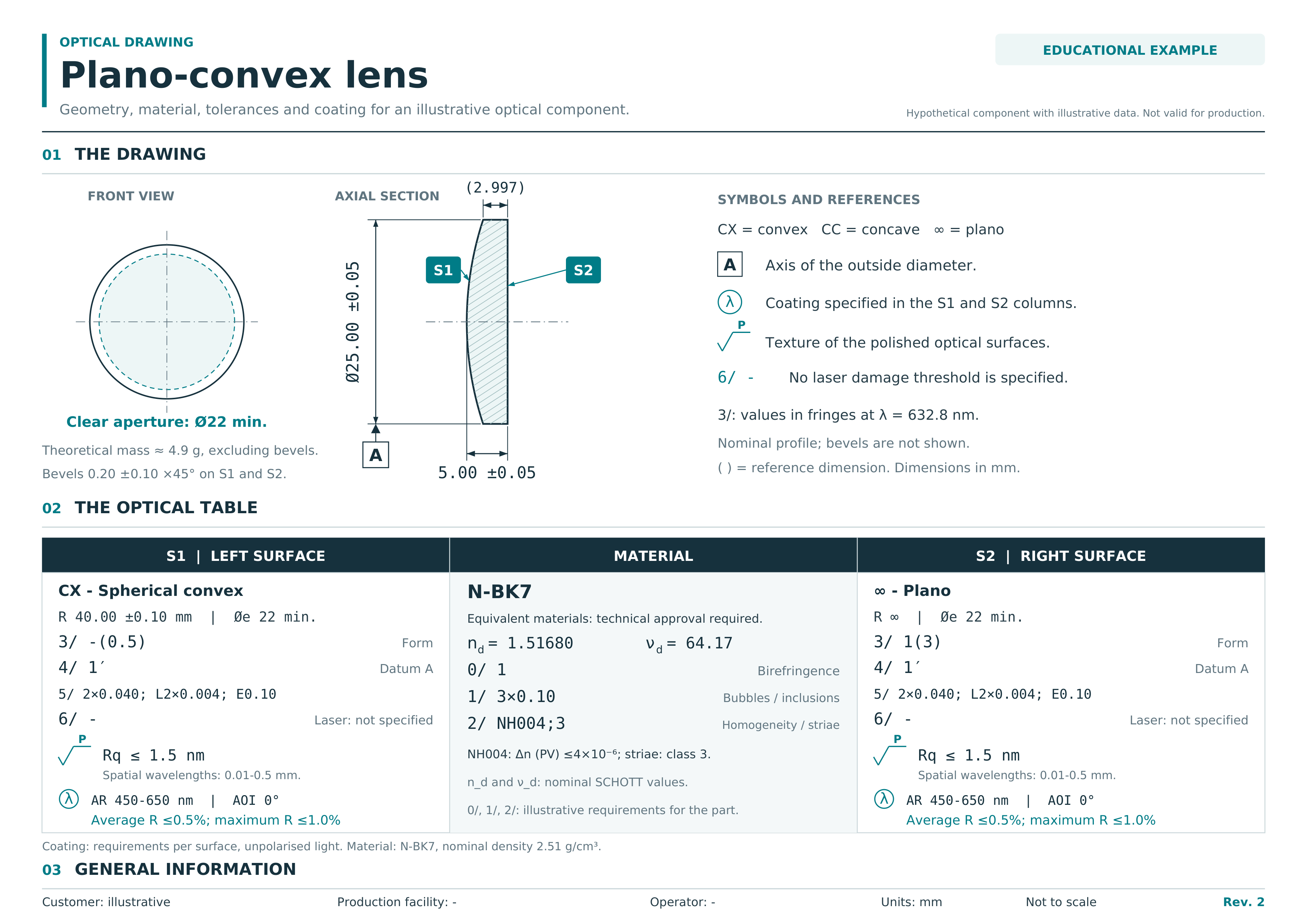
Figure 1. Educational example: the codes refer to the illustrative requirements of the lens shown.
The general information section
At the bottom of the drawing are indicated the general information relating to the customer, the production facility, the operator, and the units of measurement.
ISO 10110 Drawing Indications and Tolerance Codes
In the example discussed here, seven indication codes appear after the description of the lens geometry: 0/, 1/, 2/, 3/, 4/, 5/, and 6/. Each identifies a specific category of component tolerances or requirements:
- 0/ stress birefringence tolerance
- 1/ bubbles and inclusions tolerance
- 2/ refractive-index homogeneity and striae tolerance
- 3/ surface form tolerance
- 4/ centring and tilt tolerance
- 5/ surface imperfections tolerance
- 6/ laser-induced damage threshold
0/ Stress Birefringence Tolerance
Indication 0/ specifies the maximum optical path difference (OPD), expressed in nanometres per centimetre of optical path, permitted between the orthogonal polarization components of a light beam. The OPD is generated by stress-induced birefringence within the optical material.
Birefringence is the variation of refractive index with polarization orientation. Optical glass is normally isotropic, but residual pressure or stress can make it optically anisotropic. ISO 10110-18 therefore expresses the limit as the maximum OPD between two orthogonal polarization components after one centimetre of propagation through the material: a lower numerical value represents a tighter requirement.
1/ Bubbles and Inclusions Tolerance
Indication 1/ specifies the permitted number and size of bubbles and inclusions within the bulk material. The basic notation is 1/NxA, where N is the maximum number of imperfections of grade A and A is the value, expressed in millimetres, corresponding to the square root of the projected imperfection area. For example, 1/3×0.10 permits up to three imperfections of grade 0.10, subject to the ISO accumulation and concentration rules.
2/ Inhomogeneity and Striae Tolerance
Indication 2/ covers refractive-index homogeneity and striae in the material. Homogeneity is the gradual variation of n_d within the glass; striae are localized inhomogeneities generated during melting. A common notation is 2/A;B, where A defines the homogeneity requirement and B the striae requirement.
For compatibility with existing drawings, ISO 10110-18 retains the legacy homogeneity classes from 0 to 5: as the class number increases, the maximum permitted refractive-index variation decreases. The standard also provides the indicators NH100, NH040, NH010, NH004, NH002, and NH001.
The NH indicators correspond respectively to maximum peak-to-valley refractive-index variations of 100, 40, 10, 4, 2, and 1 x 10^-6. The striae requirement is stated using the applicable class defined by the standard.
3/ Form Tolerance
Indication 3/ defines the permitted surface-form deviation from the nominal shape. In a compact notation such as 3/A(B/C), A is the power-deviation limit, associated with power or sagitta departure; B is the residual surface irregularity; and C is the rotationally invariant irregularity.
Surface form is normally evaluated by interferometry, analysing the wavefront associated with the difference between the actual and nominal surfaces. This measurement concerns surface form, not micro-roughness, which belongs to surface texture and is specified separately under ISO 10110-8.
ISO 10110-5:2026 identifies nanometres as the preferred unit for surface-form deviations. Fringe spacings remain permitted only when the reference wavelength is explicitly stated; the standard also allows more detailed indication forms according to the errors that need to be controlled.
4/ Centring and Tilt Tolerance
Indication 4/ covers centring and tilt tolerances. It describes the alignment of the optical axis, or of individual optical surfaces, relative to the datum axis or datum system defined on the drawing. The error may be expressed as an angular deviation, for example in arcminutes.
For rotationally symmetric elements, misalignment may also be expressed as Edge Thickness Variation (ETV), the thickness difference measured between opposite edge positions under the stated conditions. A common notation is 4/C, where C is the maximum permitted angular error relative to the specified datum. The current reference is ISO 10110-6:2025.
5/ Surface Imperfections Tolerance
Indication 5/ defines the acceptable level of localized surface imperfections, long scratches, and edge chips. In the dimensional form 5/NxA, N is the permitted number of imperfections of grade A and A corresponds to the square root of the affected area.
Bubbles and inclusions within the bulk glass are not covered by indication 5/: they are material imperfections specified under 1/. Indication 5/ instead covers defects such as scratches, digs or surface pits, long scratches, and edge chips, with separate limits where required by imperfection type.
Another widely used system is U.S. Standard MIL-PRF-13830B, which describes cosmetic surface quality with a scratch-dig pair in the form SD X-Y. The scratch number is a visual grade obtained by comparing scratch brightness with calibrated reference standards; the dig number states the maximum permitted pit diameter in hundredths of a millimetre. For example, a dig value of 40 corresponds to a maximum diameter of 0.40 mm: it is not a number for bubbles within the bulk glass.
6/ Laser-Induced Damage Threshold
Indication 6/ specifies the laser-induced damage threshold under ISO 10110-17. The requirement must define the irradiation conditions, including wavelength, pulse duration, beam profile and test method. In the educational drawing, 6/- means that no laser-damage threshold requirement is specified for this example.
Surface Texture and Roughness
Surface texture is the residual surface structure after the nominal form has been removed. ISO 10110-8 distinguishes high-spatial-frequency errors, associated with roughness, from mid-spatial-frequency errors, associated with waviness. Ra is the arithmetic mean profile roughness, whereas Rq is the root mean square (RMS) profile roughness; a specification can also define areal parameters and the spatial evaluation bandwidth. Surface texture must not be confused with the surface-form tolerance specified by 3/.
Coating (circled λ)
A coating is a thin layer of material deposited on the lens surface to modify reflectance, select polarization, or separate different spectral regions. In the drawing, surfaces to be coated are indicated by a circled λ symbol. Next to this symbol, or in the section below, the following are specified:
- the maximum permitted residual reflectance
- the wavelength range over which the coating must operate
- the coating type and performance requirements (antireflective, reflective, dichroic, or polarizing)
An antireflective coating reduces unwanted reflection; a reflective coating turns the surface into a high-efficiency mirror; a dichroic coating selects specific spectral regions and reflects or transmits others.
The drawing states the maximum permitted residual reflectance and the operating wavelength range. In our Coating department in Scandicci, internalized to maintain direct control of this process, we use spectrophotometers to measure the percentage of light reflected or transmitted at different wavelengths.
The technical drawing defines the dimensions and manufacturing tolerances agreed upon between suppliers and customers and is fundamental to ensuring that optical components meet the specifications required in final applications.
Reading an optical technical drawing correctly requires knowledge of the ISO 10110 series, familiarity with symbols and notations, and an understanding of the physical meaning of each requirement. This is why we invest in training our team: technicians, engineers, and specialists in metrology, coating, polishing, and generation must share the same technical language. It is the foundation of the quality built into every optical component that leaves our facility.
Our technicians verify that the tolerances are consistent with the final application and identify ambiguities, conflicting requirements, or manufacturability issues during the technical review of the customer’s drawing. They also identify the most critical requirements and those that have the greatest impact on the manufacturing and metrology strategy.
In our industry, misreading a tolerance means risking a component that does not achieve the required performance. Even small numerical differences can change the process, metrology, lead time, and cost. Before production begins, we therefore analyse the drawing, verify that requirements and priorities are explicit, and define the most appropriate manufacturing route.